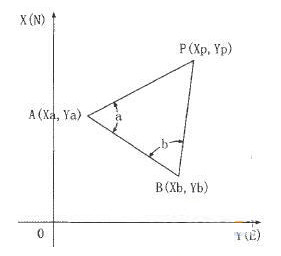
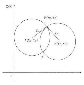
1 Introduction In engineering measurement, the calculation of internal data accounts for a very important proportion. The accuracy and speed of calculation of internal data directly determines whether the measurement work can be completed quickly and smoothly. The calculation method of the internal data and the precision it needs to achieve are directly dependent on the instruments used in the field, the specific lofting targets and the office software and calculation methods used in the internal calculation. Computer Aided Design (AutoCAD) is an emerging technology application developed in the early 1980s. It is now widely used in various fields and greatly improves the efficiency of engineers and technicians. 2 AutoCAD's typical internal data calculation Encrypting control points in the survey area often uses angle-angle intersections or ranging intersections or a combination of the two. If we use mathematical formulas to calculate, it is very cumbersome and difficult to check for errors, such as dangerous rounds in resections. on. On the contrary, if we use AutocAD to plot calculations, it is much simpler. The two methods of angle measurement and ranging are described as follows: (1) Front angle measurement meeting As shown in Fig. 1, A and B are control points with known coordinates, P is the point to be determined, and angles a and b have been observed at two points A and B. Figure 1 front angle intersection method We can use AutocAD system software to draw two points A and B on the desktop according to the coordinates of A and B. Connect AB point to get AB line segment, then rotate AB line segment a and b angle with point A and point B respectively. (The direction can be visually distinguished from the figure). Use the ID command to select the intersection point P, you can get the P point coordinates. If the graph has a check condition, the coordinate difference can still be calculated. If the need is met with an approximate adjustment, the average calculation can be performed on the graph and marked. (2) Distance intersection method As shown in Fig. 2, A and B are control points with known coordinates, P is the point to be requested, and the instrument is directly placed on point P, and the distances Sa and Sb are respectively measured by the total station. Figure 2 Distance intersection method We can also use the AutocAD system software to draw two points A and B according to the coordinates of A and B. Connect the AB point to get the AB line segment, then take the points A and B as the center, and take the sa and sb as the radius. In the circle, P point and P1 point are obtained (according to the orientation of the scene, it can be visually distinguished from the figure that one point P is the desired one, and the other point P1 is the virtual point, which is not needed). Use the ID command to select the intersection point P, you can get the P point coordinates. In the actual work process, we usually combine the front angle measurement intersection with the front distance intersection, of course, it is not necessary to complete all the conditions. In addition, for the above several applications of coordinates, it should be noted that Auto. The coordinate order in cAD is different from the geodetic coordinate system in our measurement, that is, the correspondence between x coordinate and Y coordinate should be noted. 5730 Led Chip,5730 Red Led Chips,White Smd Led Chips,Led Diode Lights Chip Shenzhen Huangtai Photoelectric Co.,Ltd. , https://www.huangtailightstrip.com
