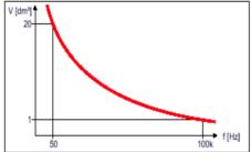
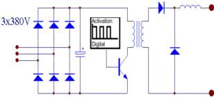
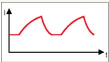
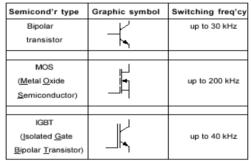
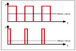
2. Implementation of digital welding machine Figure 1 schematic diagram of the main circuit of the analog welder The welding power supply has the characteristics of low voltage and large current. In order to meet the requirements of the welding power source, it can be realized by various design methods. In the design of the welding power supply, the design of the transformer is the key. In the welding power supply, the transformer satisfies the matching requirements of current and voltage on the one hand, and electrically isolates the power transmission circuit and the welding circuit on the other hand. More importantly, the position of the transformer in the energy transfer circuit determines the volume and quality of the welding power source. Figure 2 Simulated welder output current waveform Figure 2 is a block diagram of the main circuit of the analog welder. This power supply consists of a power frequency transformer, a three-phase rectifier bridge, and a transistor group. The transistor group acts as a series resistor of the load in the loop. The transistor group operates in the amplification region, and the unnecessary voltage in the solder is consumed between the C and E poles of the transistor group, so the power consumption is extremely large, and the transistor group needs water cooling. The advantage of this type of welder is that the response speed is fast, and the disadvantage is that the transistor group consumes a large amount of energy, so it has basically been replaced by other types of power sources. Figure 3 main circuit block diagram of the switching power supply In actual work, due to the use of IGBTs, MOSFETs or bipolar transistors as switching devices, there will always be a certain power loss, but this loss is negligible compared to the loss of the analog welder. Taking a 20KW switching power supply as an example, since modern power electronic switches are mostly voltage-driven, the required current is extremely small, and the control circuit only needs a few watts of power to meet the requirements. In addition to high efficiency, another advantage of switching power supplies is their high operating frequency. The higher the operating frequency of the switching power supply, the smaller the ripple of the loop output current and the faster the response speed, so the welder obtains better dynamic response characteristics. Table 1 lists the different switching devices used in the switch-type welder and the typical switching frequencies corresponding to them. Table 1 Switching Devices Used in Switching Power Supplies - Switching Frequency In order to adjust the power output over a wide range in the switching power supply, the ratio (or duty cycle) of the on-time to the off-time of the trigger pulse must be adjustable. As shown in Fig. 4, a high duty ratio outputs a higher average current value, and a lower duty ratio outputs a lower average current value. This adjustment method is called pulse width adjustment (PWM). At present, almost all of the fully controlled power switch inverter power supplies and switching power supplies use PWM control circuits. Figure 4 Output current of the switching power supply The development of welding power from analog welders to switch welders has actually completed the leap from welding to digital power. The digitization of the main circuit of the welding power source has improved the performance of the welding power supply in two aspects: Figure 5 Transformer volume-operating frequency curve Therefore, the mass, volume and frequency of the transformer are inversely proportional. The higher the operating frequency of the transformer, that is, the larger f, the smaller the number of turns N1 of the transformer winding and the smaller the cross-sectional area S of the core, so the smaller the mass and the smaller the volume. Figure 5 shows the transformer volume-frequency curve. If the transformer is placed behind the switching device, as shown in Figure 6, we get the main circuit structure of the arc welding inverter power supply. At this time, the operating frequency of the transformer is increased from 50 Hz to the 20 KHz inverter frequency we often mention, and some designs can even reach 100 kHz. Therefore, the arc welding inverter power supply has the advantages of small size and light weight compared with the switching power supply. Figure 6 Inverter power supply main circuit block diagram The arc welding inverter power source originates from the thyristor inverter arc welding power source. Although the voltage and current capacity of the thyristor can be made higher and the control power is large, since it is a semi-controlled switching device, it cannot be turned off once triggered. Broken, so forced shutdown is required, resulting in a complicated circuit. At the same time, the switching speed of the thyristor is slow, the working frequency is low, and it can only work in the range below 5KHz. Since the 1980s, power switching devices have developed greatly in terms of types and capacities (current and voltage levels). From the current application point of view, the use of MOSFETs, IGBTs as power switches is the mainstream of arc welding inverter power supply, the trend toward the development of intelligent power modules (SPIC). Previous Next
With epidemic of the noval coronavirus COVID-19 (SARS-CoV-2) out-breaking currently, many biotech companies are sourcing lab plastic consumables worldwide to control the spreading. We also received many inquiries from different countries. But most inquiries are mainly for some items of us. This page is to help the researchers who need to find out our products that used in COVID-19 quickly, hope it helps.
However, any your inquiries are welcome, please never mind to contact us!
Antigen Extraction,Acid Extraction Tubes,Nasopharyngeal Swab,Antigen Rapid Test Cassette,Test Cassette Yong Yue Medical Technology(Kunshan) Co.,Ltd , https://www.yongyuelab.com
The welding machine is developing in the direction of digitization and contains two aspects. One is the digitization of the main circuit and the other is the digitization of the control circuit.
2.1 Digitalization of the main circuit 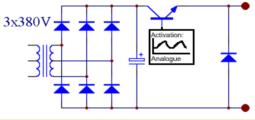
Unlike the analog welder, the transistor group operates in the switching state in the switching power supply, and the main circuit is shown in FIG. The switching power supply mainly consists of a power frequency transformer, a rectifier bridge and a semiconductor switch. The semiconductor switch is periodically turned on/off according to a fixed frequency (eg, 20,000 times per second on/off, corresponding to a frequency of 20 kHz). If the circuit shown in Figure 3 is analyzed with an ideal switch, whether it is in the on state or In the off state, the loss of the switch is zero. 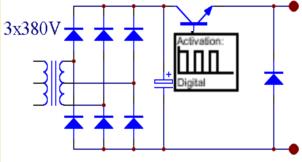
1. The power loss of the welding power source is greatly reduced, so that the efficiency of the welding power source is more than 90%.
2. As the operating frequency increases, the ripple of the loop output current is smaller and the response speed is faster, so the welder obtains better dynamic response characteristics.
In the design of the transformer, we often use the formula 1,  (Formula 1)
Where: V1 is the induced electromotive force of the transformer once, the unit is V;
Bm is the maximum value of the magnetic flux density of the transformer core material, unit T;
N1 is the number of turns of the primary winding of the transformer;
S is the core cross-sectional area in cm2;
f is the working frequency of the transformer, in Hz; 