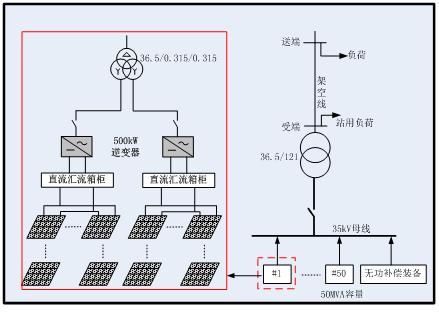
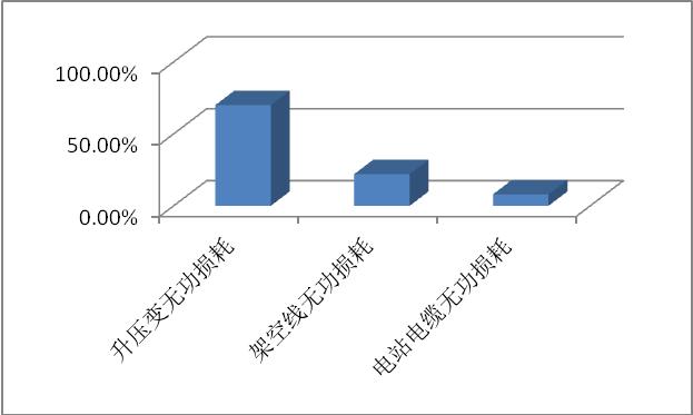
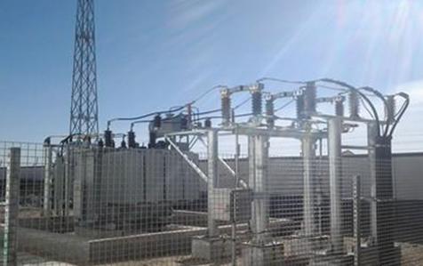
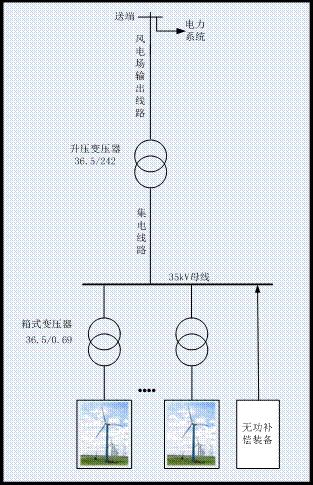
I. Calculation of reactive power configuration of photovoltaic power station Generally, the reactive power configuration analysis of photovoltaic power stations needs to be carried out in accordance with Technical Regulations for GB 19964-2012 Photovoltaic Power Plant Access Power System and Technical Specifications for GBT 29321-2012 Photovoltaic Power Plant Reactive Power Compensation. PV power plant inverters can issue reactive power, but considering that the power station can provide a certain amount of reactive power reserve capacity for the system, reactive power compensation devices need to be configured. The reactive power compensation capacity shall be determined in conjunction with the actual access to the power grid. The capacitive reactive power compensation capacity of the configuration shall be the sum of the reactive power loss of the step-up transformer, the reactive power loss of the line, and the line charging power at the rated output of the photovoltaic power station. The inductive reactive power compensation capacity should be able to compensate for the charging power of all the lines. In general, the proportion of the total reactive power loss occupied by step-up reactive power loss is close to 70%, and the reactive power loss caused by the overhead line in the outgoing line accounts for more than 22% of the total reactive power loss. The proportion of losses is about 8%; in addition, the inductive reactive power demand of the power station is far less than the capacitive reactive power demand. For a reactive power compensation device such as SVG, continuous regulation from rated inductance to rated capacitance can be realized. Therefore, SVG capacity can be configured with capacitive reactive power demand. In order to reduce the calculation workload, an approximate calculation can be performed. The reactive power compensation capacity only needs to consider the step-up change reactive power loss, and then it can be converted according to the coefficient. Transformer reactive loss calculation formula is: In the formula, QT is the reactive power loss of the transformer, kvar; UK % is the transformer short circuit voltage percentage, I0% is the transformer no-load current percentage; S is the transformer apparent power, kVA; SN is the transformer rated capacity kVA. In general, the step-up short-circuit voltage is 6.7%, and the no-load current is 0.4%. According to this parameter, the reactive power demand for step-up transformer is approximately 7% of the total capacity of the power station, and the total reactive power demand of the entire power station is 10%; if the grid-connected photovoltaic power plant uses a single step-up, ie, boosts to 35 kV on-grid, it The reactive power compensation capacity can be configured as 10% of the total capacity of the photovoltaic power station. Considering the requirements of photovoltaic power plant capacity for access to the grid voltage level and the restrictions imposed by the actual grid point on the voltage level, the photovoltaic power plant grid connection project may require two boosts. If the photovoltaic power plant access system voltage level is 110 kV, it is still necessary to proceed. Only 35 kV/110 kV boost can be connected to the grid. Generally, the 35 kV/110 kV step-up short-circuit voltage is 10.5% and the no-load current percentage is 0.67%. Therefore, if two boosts are used, The reactive power compensation capacity can be configured as 20% of the total capacity of the photovoltaic power station. II. Calculation of Reactive Power Configuration of Wind Farm It is generally necessary to perform reactive power configuration analysis of wind farms based on the GBT_19963-2011 Wind Farm Access Power System Technical Regulations. The reactive power loss of a wind farm is mainly composed of four parts: 1) Box-type transformer: The box-type transformer boosts the voltage of the fan from 690V to 1OkV or 35kV, and one fan corresponds to a box-type transformer. 2) Collecting line: The power of the fan is boosted by the box transformer and then sent to the booster station of the wind farm through the collector line. 3) Step-up transformer: The step-up transformer in the step-up station of the wind farm boosts the power sent by the collector line and sends it. 4) Wind farm transmission line: The step-up transformer boosts the wind power and enters the power system through the transmission line. In the same way, the transformer losses in the above reactive power losses are the largest, and the calculation formula is the same. The box-type transformer has a short-circuit voltage percentage of 4.5%, a no-load current percentage of 0.9%, and a reactive power configuration capacity of 5.4% or more. The percentage of short-circuit voltage of step-up transformer is 9%, the percentage of no-load current is 0.19%, and the reactive power configuration capacity should be above 9.2%. Coupled with the reactive power loss of the collector circuit and the outgoing circuit, the reactive power configuration of the entire wind farm should be above 20%. Therefore, the reactive power configuration capacity of a wind farm is generally configured according to a 20% ratio of the power station capacity. Subsea Gaskets ,Api17D Gasket,Sbx Ring Gasket,Subsea Gasket WENZHOU JINGWEI SEAL TECHNOLOGY CO., LTD , https://www.ringjoint-gasket.com
Figure 1 System topology of desert power station 


