In the injection mold, the design of the parting surface directly affects the quality of the plastic part, the structure of the mold and the difficulty of operation, and is one of the key factors for the success of the injection mold design [1]. With the wide application of CAD/CAM technology in the mold manufacturing industry, the mold design has also changed from the traditional two-dimensional design to the three-dimensional design. Among the many CAD/CAM software, Pro/E uses a single database and parametric design method to integrate product design, mold design and CNC machining. Its powerful functions make it a leader in the industry. In the Pro/E mold design, the existing product model is used to establish the mold assembly model, set the shrinkage rate, the thickness of the part and the draft of the mold release, the design of the parting surface, the division of the mold volume, and the extraction of the mold parts. The mold forming part design can be completed quickly, and finally the whole mold design is completed by the expert formwork system (EMX). In the whole process, the design of the parting surface is the most complicated and time-consuming, which is the key to mold design using Pro/E [2].
1. Parting Surface <br> <br> general principle in the injection mold, opening the mold plastic articles removed interface called parting plane, which is movable, the stationary mold clamping state in a contact surface or lobe-formed The valve face of the mold. The selection of the shape and position of the parting surface is not only directly related to the complexity of the mold structure and the manufacturing difficulty, but also directly affects the quality and production efficiency of the plastic part, and is an important part of the mold design. The following principles should be followed when determining the parting surface:
(1) The mold structure should be as simple as possible. If the lateral classification is avoided or reduced, the profiled surface is used to reduce the movement and the fixed mold to reduce the processing difficulty.
(2) Conducive to the smooth demolding of plastic parts. If the mold is left as far as possible after the mold is opened, the ejector mechanism on the injection molding machine is used to avoid the lateral long distance core pulling to reduce the size of the mold.
(3) Guarantee the dimensional accuracy of the plastic parts. If possible, place parts with dimensional accuracy requirements on the same module to reduce manufacturing and assembly errors.
(4) Does not affect the appearance quality of the plastic parts. The flash edge is inevitably present at the parting surface, so it should be avoided to design the parting surface on the smooth surface.
(5) Ensure the smooth exhaust of the cavity. If the parting surface is as close as possible to the last filled cavity surface to facilitate the cavity exhaust.
In the Pro/E mold design, the parting surface is a dividing surface that divides the workpiece or the mold part into the mold volume, which has a broader meaning. It is not limited to the division of the moving, fixed or side core sliders. For the assembly and inserts in the template, the parting surface can also be divided. In order to ensure the success of the parting surface design and the design of the parting surface to segment the workpiece, the following two basic conditions must be met when designing the parting surface [2]:
(1) The parting surface must be completely intersected with the workpiece or mold part to be divided in order to form a division.
(2) The parting surface cannot intersect by itself, otherwise the parting surface will not be generated.
2.Pro/E parting surface design method There are two types of surface in Pro/E which can be used for workpiece segmentation: one is the parting surface feature generated by using Parting Surf special module; the other is to use Feature on reference model or part model Surface features generated by Surface in . Since the former obtains a surface feature of a mold assembly level, it is most commonly used because it is easy to operate and manage. The design methods involved in this article are mainly for the former. In principle, the parting surface design method can be divided into two categories [3]: First, the surface construction tool is used to design the parting surface, such as copying the surface on the reference part, sketching the section for stretching, rotating, and using other Advanced surface tools and other structural parting surfaces; second, the use of light projection technology to generate parting surfaces, such as shadow parting (Shadow) and skirt parting surface (Skirt).
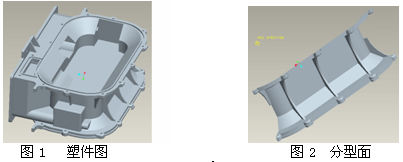
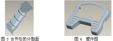
2.1 Constructing the parting surface by copying This method is based on the reference model and directly copies the surface on the reference model to generate the parting surface. It is the most flexible and commonly used parting surface construction method, especially for the complex structure. Pieces. Figure 1 shows the plastic parts of the gas metering chamber. Since the plastic parts have undercuts on all four sides, four sliders are required for the side core pulling when designing the mold. In addition, the moving and fixed mold parting surfaces need to design five parting surfaces to complete the workpiece splitting. Since each parting surface is only a part of the contour of the part, the shadow parting surface and the skirt parting surface often fail. If the surface tool is used to reconstruct the parting surface, the workload will be quite large, so the copy method is the best. s Choice. Figure 2 shows one of the parting surfaces generated by the copy.

The parting surface constructed by the copying method is an inner parting surface (cavity or core surface), which has not completely intersected the workpiece to be divided, and does not satisfy the requirements of item (1) of the Pro/E parting surface, so it is required Modify it to meet the requirements. There are two commonly used methods: one is to extend the outer boundary line to the workpiece boundary by using the surface extension (Extend) tool; the other is to construct an outer parting surface to merge with it (Merge) to meet the requirements. Another problem with replicating the parting surface is to fill the hole. Generally, the Fill loop option can be used to fill the hole. In the case of this option failure, other methods are needed to solve it.
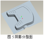
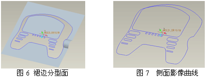
2.2 Using the Surface Modeling Tool to Construct the Parting Surface The Surface tool in the Parting Surf module can reconstruct a variety of parting surfaces with the same technique as the surface modeling in the part environment. In general, we do not use these surface tools to construct complex parting surfaces, and more are used to modify the generated parting surface to meet the requirements of the parting surface design. As shown in Fig. 2, when the surface is modified by the surface extension tool, the surface extension function cannot be realized because the stretching surface formed by the partial boundary stretching intersects with the partial parting surface. The plane construction tool (Flat) generates a plane parting surface, and then merges with the parting surface of Fig. 2 to obtain the parting surface that completely intersects the divided module, as shown in Fig. 3. In addition, this method can also be used if the fill ring option is used to fill holes. As shown in Figure 4, the holes on the surface of the part are chamfered and have a certain degree of draft. The small core needs to be placed on the side of the fixed mold. When the outer surface and the inner wall of the hole are selected to replicate the parting surface, since the bottom edge of the hole is not the inner ring of the parting surface, the filling ring option cannot be directly used to complete the repair of the hole, so it is necessary to construct the bottom plane and then The fusion is obtained to obtain the parting surface of the hole.

Shadow Parting Surface 2.3 The principle of the shadow parting surface is that when a light source (the direction of which is opposite to the mold opening direction) is irradiated on the reference model, the system copies the surface of the reference model that is illuminated by the light source to produce a shaded surface body. And fill the holes in the surface, and then automatically extend its outer boundary to the surface of the workpiece to be split to create a covered shadow parting surface. Figure 5 shows the parting surface obtained directly from the shadow of the plastic part of Figure 4.

The shadow parting surface is a fast and efficient parting surface construction method. However, this method has great limitations. On the one hand, when there is a cross in the projection direction or a partial occlusion between the curved surfaces, the generated shadow surface is often wrong; on the other hand, The external contour curve cannot modify the extension direction during the extension, so the operation often fails for complex external boundaries; further, the reference model surface must have a draft angle in the projection direction, that is, there must be no surface parallel to the projection direction. Otherwise it is difficult to ensure that the parting surface is correct, because the shadow parting surface does not allow the curve chain above or below the surface to be selected for sealing.
<br> <br> skirt skirt parting surface parting plane along the parting surface of the image side surface of the reference curve created model, a fill hole on the surface, it does not contain a reference model of the surface, and the other The parting surface generated by the method has obvious differences. Figure 6 shows the skirt parting surface of the part of Figure 5. When creating a skirt parting surface, you must first construct a Silhouette curve. The so-called silhouette curve is the contour curve of the reference model in the specified visual direction, which is the parting line when the mold is divided, as shown in Fig. 7. It generally includes several closed inner and outer rings. The inner ring is used to close the hole on the parting surface, and the outer ring is used to extend the surface boundary to the boundary where the workpiece is to be divided.

If there is a surface on the reference model that is parallel to the projection direction, the system allows you to use the chain option (Chains) in the Loop Selection to determine whether to use the upper or lower ring when constructing the silhouette curve. Therefore, when constructing the skirt parting surface using the silhouette curve, the reference model does not need to be completely drafted. In addition, when extending the outer boundary of the surface, the extension direction can be redefined. Therefore, some cases where the shadow parting surface cannot be used can often use the skirt parting surface. For the mold that needs the side core pulling, the splitting surface of the skirt cannot be used for the first parting. In general, the parting surface of the side pulling core slider can be constructed first for the first time, and then the skirt parting face is used. The remaining modules are divided twice, but the side rings should be excluded when constructing the silhouette curve.
<br> <br> Conclusions can be drawn by the above analysis, the Pro / E parting plane configuration method, a parting surface structure replication method flexible for a variety of circumstances, to select the disadvantage that the surface is more complicated, the subsequent More work, such as repairing broken holes, boundary extension, etc., in some cases, the design efficiency is low; using the surface tool to design the parting surface is often used in conjunction with the copy method, mainly for localizing the existing parting surface. Trimming to meet the requirements, rarely used alone for the construction of complex parting surfaces; shadow parting surface can automatically complete the work of hole repairing, boundary extension, etc., for complete drafting, simple boundary curve, porous surface Plastic parts are a simple and efficient method of constructing parting surfaces. However, this method has great limitations. For example, the plastic part requires complete drafting, and the surface boundary extension direction cannot be redefined, which often causes operation failure. Compared with the shadow surface, the skirt surface has less restrictions on the plastic structure. The surface boundary extension direction can be redefined. Combined with flexible and diverse side image curves, it can quickly construct a parting surface that meets the requirements. It is a commonly used parting surface construction method. In short, combining the structural characteristics of the plastic parts and the mold structure to be used, selecting the appropriate parting surface construction method is the prerequisite for ensuring the smooth design of the mold.
References [1] Editorial Board of Plastic Mold Technical Manual. Plastic mold technical manual. Beijing: Mechanical Industry Press, 1999.
[2] Pro/Engineer2001 practical tutorial, edited by Yan Lie. Metallurgical Industry Press, Beijing, 2002.
[3] Pro/ENGINEER mold design entry and practice, edited by Dai Zhizhi. People's Posts and Telecommunications Press, Beijing, 2004
Magnesium Chloride
Magnesium Chloride
Magnesium Chloride,Magnesium Chloride Snow Melting,Industrial Magnesium Chloride
WEIFANG MELTWAY CO., LTD , http://www.globalmeltway.com