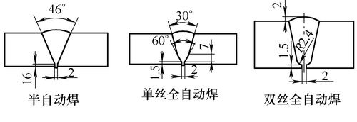
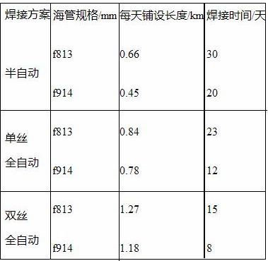
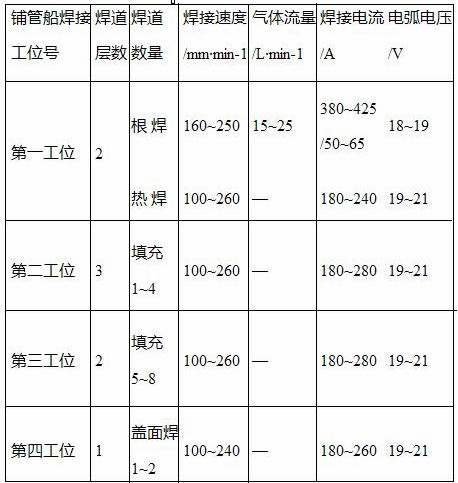
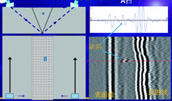
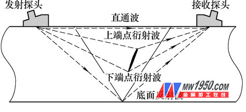
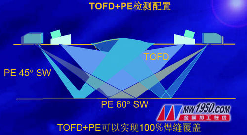
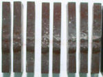
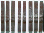
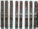
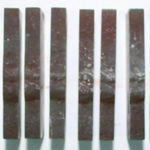
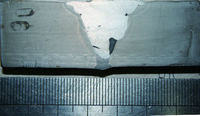
1 Overview With the rapid development of welding technology, semi-automatic welding and automatic welding technology of pipelines have been widely used in submarine pipeline welding construction, greatly improving welding speed and efficiency. Therefore, under the premise of ensuring safety and detecting the rate of hazardous defects, how to develop and apply high-efficiency and reliable non-destructive testing technology for submarine pipelines has become an urgent technical problem in the construction of submarine pipelines. In recent years, automatic ultrasonic testing technology (AUT) has been widely used in the detection of girth welds for long-distance pipeline automatic welding at home and abroad. Compared with traditional manual ultrasonic inspection (UT) and radiation detection (RT) technology, AUT has obvious advantages in detection speed, defect quantitative accuracy, reducing environmental pollution, and reducing work intensity. In the past, AUT technology was mainly used in the automatic welding of sea pipe, and the semi-automatic welding of pipes was mostly based on RT detection. The feasibility study of the application of automatic ultrasonic testing technology in semi-automatic welding and welding of submarine pipelines is carried out to improve the accuracy of AUT defect detection of semi-automatic welding heads of submarine pipelines, which is the basis for ensuring the laying and safe operation of sea pipes. 2. West 2nd line sea pipe welding process and its assessment The Shenzhen-Hong Kong Spur Line of the Second West-East Gas Pipeline undertaken by PetroChina Marine Company, the submarine pipeline of the Shenzhen-Hong Kong Expressway includes two pipelines from the Qiyuling to Dadaodao Sea Pipeline and the Dachao Island to Longgutan Sea (Hong Kong Branch) pipeline. The parameters of the pipeline are shown in Table 1. Table 1 Main parameters of the pipelines of the Shenzhen-Hong Kong branch line of the Second West-East Gas Pipeline 1) The West 2nd line sea pipe welding process project initially prepared three sets of welding schemes, namely the welding method of double wire automatic welding, monofilament automatic welding and core semi-automatic welding, and the three sets adopted different groove forms. As shown in Figure 1, the pipelaying speeds of the three welding processes are shown in Table 2. Figure 1 Groove form and its size Semi-automatic welding is slower, but the process is more mature and the requirements for welding equipment are not high. Automatic welding is highly efficient, but requires high joint processing and grouping. Since the straight line distance of the project sea pipe is not long, the water in the area is shallow, the work of trenching is very large, and the laying speed of the sea pipe is determined by the trenching speed. Therefore, the premise of the progress and quality of the project can be guaranteed in all three welding processes. Under the comprehensive consideration, the semi-automatic welding process was finally decided, and the non-destructive testing of the weld was performed by a fully automatic ultrasonic testing method. Since the industry has always had a fully automatic ultrasonic testing method that can only be used for fully automatic welding, there is no deep understanding of the applicability of semi-automatic welded joints. Therefore, in order to make the automatic ultrasonic testing technology meet the project quality requirements, the pipeline can be safely operated for 30 years. The realization of the goal, we use the combination of phased array and TOFD detection method, at the same time strict control of welding parameters, number of bead layers and weld bead, welding groove machining for machining, and simulation of preparation of welding defect test pieces, The defect test pieces are separately tested by AUT, RT and metallographic methods to ensure the reliability of AUT detection. Table 2 Pipelaying speed of different welding processes (2) Welding procedure qualification test is carried out for the welding process used. The root welding is performed by STT welding. The heat welding, filling and covering are self-shielded. The welding direction is downward. The root welding preheating temperature is 100 °C. The temperature is 100 to 150 ° C, and the welding material is JM-58 (f1.2 mm) and Fanshield 81N1 (f2.0 mm). The specific number of bead layers, the number of passes and the welding process for each station are shown in Table 3. Table 3 Welding parameters 3. Fully automatic ultrasonic testing technology The AUT method divides the weld into several zones along the thickness direction. Each zone is detected by one or two pairs of focusing probes, and also by non-focusing probes. Therefore, the detection system is required to be multi-channel; the detection results are graphically displayed. A scanning, B-scan and ultrasonic diffraction time difference method (TOFD) three display modes; the scanner uses automatic scanning and automatic coupling in the pipe loop direction, comprehensively detects the entire weld thickness direction zone, and automatically compares the results and The acoustic coupling status is displayed on the image as shown in Figure 2. Figure 2 AUT defect status display image 4. Analysis of semi-automatic welding seam mechanism of automatic ultrasonic testing (1) Principle of semi-automatic welding seam detection by AUT Diffraction time difference method Ultrasonic detection TOFD is an ultrasonic detection method that uses the diffraction wave signal of the defect end point to find defects and measure the defect size. Generally, the longitudinal wave oblique probe is used, and the one-shot-one-receiving mode is adopted. ,As shown in Figure 3. TOFD can detect various strike defects, because TOFD uses the diffraction signal for detection, which can accurately measure the depth and height of defects; however, TOFD has a dead zone on the surface and bottom. Figure 3 TOFD detection one shot and one receiving mode Ultrasonic phased array technology is a software that can individually control the excitation time of each wafer in the phased array probe to control the beam angle, focus position and focus size. Phased array technology enables linear sweeps, sector scans, and dynamic depth focusing for wide beam and multifocal features, so detection speeds can be faster. Ultrasonic phased array technology for real-time color imaging, including A/B/C/D and S-scan, for easy interpretation of defects. Ultrasonic pulse echo detection (PE) is a common ultrasonic inspection method that covers the root of the weld and the surface area of ​​the weld. The principle of AUT detection is shown in Figure 4. Two phased array TOFD probes are used to detect the left and right sides of the weld. The focus method is fan-shaped, and the weld is detected at multiple angles. Defects in various directions are detected to ensure 100% coverage of the weld. In addition, the PE probe can cover the blind zone of the TOFD, which can better detect the root and surface. Since the two detection technologies are used together for inspection, the weld can be covered by 200%. Even if the groove changes (such as the gap between the mouth gap or the filling area), it will not affect the test result, so it can be used. Semi-automatic weld seam inspection. The TOFD data and phased array data can be interpreted complementarily to make the determination of defects more accurate (see Figure 5). Therefore, an accurate inspection of the weld seam of the semi-automatic welding can be performed. Figure 4 shows the principle of AUT detection (2) Calibration test block production The f813mmAUT semi-automatic welding calibration test piece designed according to the welding groove form of the West Second Line project is used to evaluate the groove size, groove angle and weld bead arrangement of the welded joint according to the welding procedure, and the weld bead is partitioned ( See Figure 6), and added the surface groove and the root groove, the groove and the undercut simulation groove, and determined the orientation of the target reflection zone of the root, the blunt edge, the heat welding and the filling zone; the AUT detection calibration was completed, and the submarine pipeline was semi-automatically guaranteed. Non-destructive testing defect detection rate, defect type evaluation and detection accuracy of welded joints. Figure 6 Weld Arrangement and AUT Detection Partition 5. Non-destructive testing comparison test for submarine pipeline welded joints (1) Simulation of simulated welding defect test pieces According to the above welding process, we used the f813mm×22.2mm tube to make the simulated defect test piece, and welded 4 defective test piece tubes, each of which was prefabricated with cracks, pores and slag inclusions. 7 different welding defects, such as unfused, with a defect length of about 350 mm. Through the non-destructive testing of the four simulated defective tubes, according to the standard ASTM E1961 and API1104, the seven defects simulated were successfully simulated and achieved the intended purpose. (2) Detection and comparative analysis of simulated welding defect test specimens AUT and RT tests were performed on the simulated defective test tubes, and the defects detected by AUT and RT were marked on the test tubes. Both test methods detected weld defects in the same area. The length of each of the seven defects was 300 mm on the test tube, and the following tests and analyses were carried out. First, the removed defective test piece was cut into 30 pieces, each having a thickness of 7.28 mm. The left side of the test piece is set to A, and the right side of the test piece is set to B, and macroscopic metallographic detection is performed piece by piece, as shown in Fig. 7. Figure 7 test piece Second, the metallographic profile test results are as follows. Metallographic profile test results and defect inspection results Crack: The root defects found in sections 1A to 5A, 14A to 15A are consistent with the location and size of the upstream defects detected by the AUT; the roots found in sections 6A to 29A, one layer filled, and the second layer of defects are located in the downstream defect location detected by the AUT. The size is consistent; the cumulative length of defects is about 211mm. RT detection detected unfused defects, the cumulative length of defects was 140mm, less than the profile and AUT test results Incomplete penetration: starting from 4A to profile 28A, continuous defects were found at the root of the weld, filling one layer, filling two layers, and filling three layers. The cumulative length was 205 mm, which was consistent with the AUT test results. RT test also detected incomplete penetration and unfused defects Slag inclusion: From 1A to 30B profile, defects are found in the weld seam of the test piece and filled in three layers. The cumulative length of the defect is about 218mm, which is basically consistent with the AUT test results. RT detection detected 290 mm of unfused defect and 20 points of slag inclusion. The three test results are basically consistent Porosity: Except for the 22A section, defects are found in other sections. The defect location is located at the root, middle and surface of the weld, which is basically consistent with the AUT test results. The undetected defect was detected by RT detection at 251 mm, and the pores and slag were 9 points. The three test results are basically consistent Unfused: Defects were found in multiple sections of the profile inspection. The defect location was located in the weld seam with three layers, four layers, and six layers, which were basically consistent with the AUT test results. RT detection detected multiple unfused defects. The three test results are basically consistent Burn through: defects are found in multiple sections. The defect location is located at the root of the weld, filled in one layer, and filled in two layers, which is basically consistent with the AUT test results. RT detection detected burn through defects. The three test results are basically consistent The sidewalls are not fused: except for the 10B section, defects are found in other sections, and the defects are located at the root, middle and surface of the weld, which is basically consistent with the AUT test results. The undetected and slag inclusion defects were detected by RT detection. Third, in order to facilitate the analysis, the typical profile and the sample AUT, RT results are plotted, the test results are shown in Figure 8. (b) RT test results 1A 5A 6A (a) Profile test results (b) RT test results Figure 8 Typical sample defect detection results Figure 8 Typical sample defect detection results 6. Conclusion (1) By conducting AUT and RT non-destructive testing comparison verification test, the AUT technology detection accuracy and defect detection rate are verified. The AUT technology can detect the spatial position and space size of the welded joint defect, and ensure the follow-up repair quickly and accurately. The efficiency of on-site repair construction. (2) Through the inspection of weld joints containing defects and non-defective profiles, the accuracy of detection of defects such as slag inclusion, pores, unfused, incomplete penetration, burn through and cracks by AUT and RT non-destructive testing techniques was tested and compared. It has played a good role in guiding engineering applications. Sf6 Gas Density Meter,Natural Gas Density Meter,Lpg Density Meter,Oxygen Density Meter wuxi kaifeng pressure gauge co., ltd , https://www.wxkfmanometer.com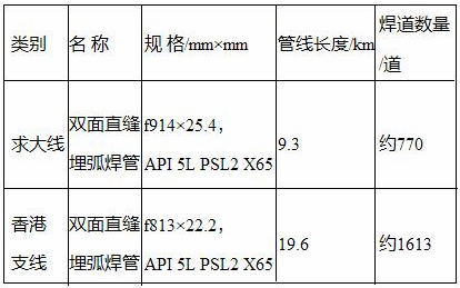

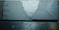

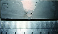
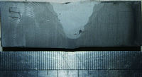
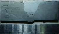
7A 9A 13A 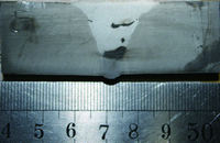
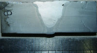
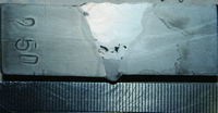
17A 25A 30A 

AUT test results 
Unfused 25mm 
Slag 20 points