First, the structure characteristics of twist drill
Twist drill is the most commonly used hole machining tool. The straight main cutting edge of this type of drill bit is long, the two main cutting edges are connected by the chisel edge, the chip pocket is spiral (for easy chip removal), and a part of the spiral groove constitutes the front knife. The face, rake face and apex angle (2Ø) determine the size of the rake angle g, so the front angle of the drill tip is not only closely related to the helix angle, but also affected by the blade inclination angle. The structure and geometric parameters of the twist drill are shown in Figure 1.
   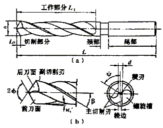
D: diameter y: transverse blade bevel angle a: back angle b: helix angle Ø: apex angle d: core diameter L: working part length
Figure 1 Schematic diagram of the structure and cutting part of the twist drill
The transverse blade bevel angle y is the angle between the chisel edge and the main cutting edge in the projection of the end face, and the size of the y and the length of the chisel edge depend on the size of the relief angle and the apex angle at the core. When the apex angle is constant, the larger the back angle, the smaller y and the longer the traverse edge (generally y is controlled within the range of 50° to 55°).
Second, the force analysis of twist drill
The force of the twist drill is more complicated, mainly including the deformation resistance of the workpiece material, the friction between the twist drill and the hole wall and the chip. Each bit of the drill bit will be subjected to three components of Fx, Fy and Fz.
   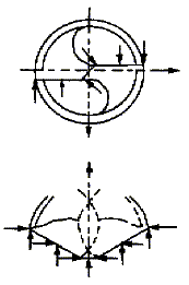
Figure 2 Force analysis of twist drill cutting
As shown in Figure 2, in the ideal case, the cutting edges are substantially balanced with each other. The remaining forces are axial and circumferential forces, which create torque and consume the main power during machining. Twist drill produces transverse bending, longitudinal bending and torsional deformation under the action of cutting force, among which the torsional deformation is the most significant. The torque is mainly generated by the cutting force on the main cutting edge. According to the finite element analysis, the torque on the cutting edge of the ordinary drill tip accounts for about 80% of the total torque, and the torque generated by the chisel edge accounts for about 10%. The axial force is mainly generated by the chisel edge. The axial force generated on the chisel edge of the ordinary drill tip accounts for about 50% to 60%, and the axial force on the main cutting edge accounts for about 40%.
   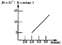
Figure 3 Drill diameter diameter d-stiffness Do relationship curve
Taking the diameter D=20mm twist drill as an example, the thickness of the drill core is changed under other parameters. From the stiffness curve (see Fig. 3), it can be seen that as the drill core diameter d increases, the stiffness Do increases and the deformation The amount is reduced. It can be seen that the increase of the core thickness significantly increases the axial force of the twist drill, which directly affects the cutting performance of the tool, and the rigidity of the tool also affects the geometric accuracy of the machining.
Since the chisel edge of the ordinary twist drill is a large negative rake angle, severe crushing occurs during drilling, which not only generates a large axial resistance, but also generates a large torque. For some thick core drills, such as parabolic drills (G drill bits) and some carbide drills (one of the characteristics is to increase the core thickness from 11% to 15% of the diameter of ordinary twist drills to 25% to 60%) Etc., its rigidity is good, the straightness of the drilling is good, the aperture is accurate, and the feed rate can be increased by 20%. However, the increase in the thickness of the core will inevitably lead to a longer chisel edge, which will increase the axial force and torque, which not only increases the equipment load, but also has a greater impact on the machining geometry accuracy. In addition, since the contact of the chisel edge with the workpiece is a linear contact, the positional accuracy and geometric accuracy of the hole to be machined are difficult to control when the drill tip enters the cutting state. Therefore, in order to prevent the deflection during processing, it is often necessary to pre-drill the center hole with a center drill.
In order to solve the above problem, the method of cutting the groove at both ends of the chisel edge is generally adopted to reduce the length of the chisel edge and reduce the pressing, thereby reducing the axial force and the torque. However, in actual machining, the problem of poor centering performance of the negative rake cutting and linear contact of the drill tip has not been fundamentally solved. To this end, people have been continuously researching and improving the shape of the drill tip, and the S-edge is the better way to solve this problem.
Third, the classification and characteristics of the S-edge drill tip
The S-blade drill tip is also known as the Winsland drill tip, and its chisel edge is S-shaped when viewed from the end projection. From the front projection, you can see that the middle of the drill tip is slightly drummed and has a parabolic crown. Since the S-tip is a curved edge, the drill tip enters the cutting moment and the workpiece is in point contact. Therefore, the self-centering and stability are better than the ordinary twist drill, the axial force is reduced, the cutting performance is improved, the drill life is prolonged, and the machining is processed. The hole quality is significantly improved, the positional accuracy and geometric accuracy of the hole are satisfactory, and the drilling feed rate and feed rate are further improved. According to the parabolic crown and chisel edge shape, the S-edge drill tips can be basically divided into three types, namely, a high-crown S-blade, a low-crown S-blade, and a low-crown small S-blade (see Fig. 4).
   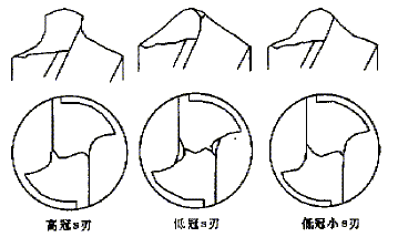
Figure 4S three types of cutting tips
High crown S blade drill tip
The high-crown S-blade drill tip is represented by the Winslow drill tip polished by the Giddings Lewis drill grinder in the United States. The machine is equipped with a special cam mechanism. The S-cutting tip cutting part (L0) is longer and the S-curve has a larger curvature. Features: Because the S part is higher (L0 is longer), the negative rake angle is basically eliminated, and even the positive rake angle cutting can be realized, so it is not necessary to add a transverse cutting groove. High grinding efficiency, suitable for grinding thick core tools. However, the tip end portion of the drill tip is relatively weak and has poor strength, and is not suitable for high-speed machining of high-hardness workpieces. The material of the drill tip is made of a material with good toughness (such as high speed steel).
Low crown S blade tip
The low-profile S-blade drill tip is represented by a German five-axis grinding machine (programmed by Numroto, Switzerland). The cutting edge cutting portion (L0) is shorter, and the S-blade crown curvature is smaller. It can be seen from the projection direction of the end face that the chisel edge is a large S shape, the middle portion can be a small straight line, and the chisel edge portion has two small grooves, which can reduce the negative rake angle of the drill tip portion.
Features: Because the cutting part (L0) is relatively short, the tip of the drill tip and the main cutting edge are better; because the crown curvature of the drill tip S is small, the self-centering and stability are better than the high-crown S-edge. After the rake angle of the chiseling edge, the drilling performance is significantly improved, which not only retains the advantages of the high-crown S-tip, but also increases the strength of the tip of the drill tip. Suitable for machining workpieces with hard materials (such as steel, cast iron, etc.). The drill material can be made of high speed tool steel, hard alloy or other high hardness materials. The grinding of such drill bits is more complicated and requires higher requirements.
Low crown small S blade drill tip
The shape of the drill tip is similar to that of the high-crown S-edge, and the chisel edge is also small S-shaped. The tip angle (2Ø) is larger than the above two types of drill tips, and the main cutting edge is short (L0 is relatively short). The coronal curvature is small.
Features: Because the main cutting edge is short, the torque during machining is small. Because the main cutting edge has high strength and small coronal curvature, the self-centering and stability are better than the high-crown S-edge. In addition, the small S-edge drill tip has no negative rake angle, so there is no need to add groove at the chisel edge, which not only controls the axial force but also reduces the torque, which can greatly improve the cutting performance. Suitable for grinding high-hardness materials (such as cemented carbide) small spiral angle drills.
Fourth, the S-edge drill tip grinding
The S-blade drill tip has a complicated shape and is difficult to grind. It is difficult to grind the ideal blade shape with a manual or ordinary drill grinder. Generally, a drill or a numerically controlled grinding machine with a special cam mechanism is required to achieve precise grinding.
Figure 5 shows the simple grinding principle of the S-edge drill tip. The grinding bit is horizontally clamped on the A-axis. When the tapered grinding wheel is in contact with the cutting edge of the tool during grinding, the B-axis rotates in the XZ plane, and the A-axis is interlocked (rotating according to the slanting helix requirement); The grinding wheel descends in the Y-axis direction with respect to the tool to form a spiral flank face and an S-shaped chisel edge.
   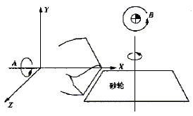
Figure 5: Simple grinding principle of the S-edge drill tip
The crown height of the drill tip is determined by the size of the arc of the conical grinding wheel (the taper is 30° to 60°) and the lift rate of the helicoid. When the lift rate is increased, the crown height is reduced, and the arc is larger. The higher the height (see Figure 5). In addition, the crown height and the radius of the S-curve are directly related to the core thickness.
To improve the cutting performance when grinding the low-profile S-edge drill tip, use a 75° angle grinding wheel to open two small grooves at the drill tip and make the angle substantially parallel to the line between the two semi-circles of S. The strength of the main cutting edge reduces the negative rake angle generated in the middle of the S-blade, so that the rake angle of the middle edge of the crown parabola is equal to zero or less than zero (r ≥ 0).
As with ordinary twist drills, the apex angle of the S-tip is also very important, and the apex angle of the drill tip is generally between 90° and 135°. As can be seen from Fig. 1, the smaller the apex angle (2Ø), the longer the main cutting edge and the greater the cutting load. Since the self-centering property of the S-tip is better, it is not necessary to reduce the geometric accuracy of the hole to be machined by reducing the apex angle (the method is not effective in the processing practice) to avoid increasing the cutting load. On the contrary, in order to improve the cutting performance of the tool and improve the tool strength and cutting speed, the apex angle of the S-blade drill tip is generally designed to be 118° or more (or even 140°). In addition, the outer edge back angle determines the size of the wedge angle when the outer edge of the drill tip is cut into the workpiece. The size of the tool wedge angle should be determined according to the hardness of the workpiece material. When the workpiece material is soft, a larger relief angle is required.
Five, S blade tip application examples
We applied the S-edge tip grinding technology to the machining of the small rod hole of the engine connecting rod and achieved good results.
Process design: 20 sequence: drilling Ø17+0.07mm, machine rotation: 200r/min, cutting speed 10.68mm/min, and the amount of cutting is 0.45mm/r. 40 sequence: reaming Ø17.5+0.05mm.
When drilling with Ø17mm ordinary twist drill, due to the self-centering performance of the drill bit and the poor drilling stability, the drilled hole often reaches or exceeds Ø17.5mm, which causes the product to be scrapped. The operator has to manually grind the drill tip, but the grinding quality is repaired. Very unstable.
We grind the drill bit into a low crown large S-edge drill tip with a top angle of 118°, an axial back angle of 7°, and a circumferential back angle of 6°. The S-edge radius is 1.5 mm, and the length of the two semi-circle lines is 0.5 mm. At the chisel edge, the 80° conical grinding wheel is used to open two slots, so that the crown rake angle is greater than or equal to zero, which can ensure the required strength of the main cutting edge of the cutter, and avoid the extrusion phenomenon caused by the negative rake angle cutting, and reduce the drilling. Cutting axial force improves cutting performance. The processing practice proves that the use of the drill bit not only effectively controls the geometric precision of the hole, but also the production efficiency is remarkably improved, and the scrap rate is greatly reduced. The comparison of the processing effect of Ø17mm ordinary drill tip twist drill and S edge drill tip twist drill is shown in the following table.
Comparison of the processing effect between the ordinary drill tip and the S-edge drill tip

Table Salt
Edible Salt,Food Grade Salt,Table Salt
Weifang Meltway Co., Ltd. , http://www.wfsnowmelting.com