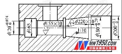
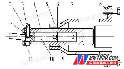
Among the products of our company, one part is specially processed. Its shape is a rectangular parallelepiped of 400 mm × 40 0 ​​mm × 800 mm. The internal structure is shown in Figure 1. figure 1 Process analysis When machining holes and tapers in the horizontal direction, if it is machined on the horizontal lathe CW 6 1100, the workpiece is 800 mm long and the shape is a square. Due to the limitation of the shape of the part, the center frame cannot be used, and only the tooling will be used. It is fixed on the turntable for processing. The stability of this processing method is insufficient, the rotation speed of the lathe cannot be too high, and the surface roughness of the inner hole cannot meet the design requirements. If it is machined on the vertical lathe CA 5112, there is also a problem of insufficient stability and it is difficult to operate. After analysis and research, the ordinary horizontal boring machine T611B can be used. The workpiece is placed directly on the workbench. The stability is very good. When machining the inner hole, as long as the machining cone is difficult, the other dimensions are processed by ordinary mast. 2. Solution Design a set of boring cone hole tool, as shown in Figure 2. The structure is as follows: The support sleeve 7 is fixed to the trampoline rotating disc by bolts 8. The mast 4 is fixed to the main shaft of the trampoline through the Morse taper shank at the tail, and a copper sleeve 6 is arranged between the mast 4 and the support sleeve 7 for sliding support. figure 2 1. Diagonal spacer 2. Tool holder 3. File 4. Mast 5. Locking wire 6. Copper sleeve 7. Support sleeve 8. Bolt 9. Pin 10. Mandrel 11. Round nut The front end of the mast has a through hole to provide space for the radial sliding of the holder 2, the file 3 and the round nut 11. The boring tool 3 is fixed to the tool holder 2 by the top wire, and the outer circle of the tool holder 2 and the outer circle of the round nut 11 are guided to drive the boring tool to move radially. The left end of the mandrel 10 has a long hole, and the holder 2 and the file 3 move axially in the long hole. The mandrel 10 is connected by a pin 9 and a mast 4, a copper sleeve 6, and a support sleeve 7, and the outer end of the pin 9 is locked by a locking wire 5. When machining the mandrel, the inclination of the mandrel and the inclination of the part are the same. The length of the long hole at the left end of the mandrel and the length of the long hole on the mast are larger than the length of the cone of the workpiece, and the width is different from the outer circumference of the holder and pin 9. A gap of 0.05 ~ 0.1 mm. 3. Working principle When the spindle rotates, it will drive the whole device to rotate at the same speed. When the spindle is extended, because the spindle is connected by the pin and the support sleeve, the horizontal direction will not be displaced, and the spindle drives the mast, the tool holder and the file to extend at the same time. Because the left end of the mandrel has a certain slope, the tool holder will drive the file to retract with the inclination, and the hole will become smaller and smaller. Similarly, when the spindle is retracted, the file will gradually extend and the hole will be larger and larger. The slope of the cone is exactly the same as the slope of the mandrel. Figure 2 shows the state in which the rake hole cutter bar is fully extended. 4. Conclusion Through the production practice, this set of tools completely solves the problem of processing the taper hole in the boring machine, and the use is reliable, which ensures the processing precision. Guangdong Jishengke Industrial Co., Ltd. , https://www.suronart.com
