Fly screens have become an essential addition to homes and buildings, providing an effective solution to keep flies and other flying insects out while allowing fresh air to circulate. These screens are designed with a fine mesh material that acts as a barrier, preventing flies from entering indoor spaces. Fly screens offer a comfortable and hygienic environment, reducing the annoyance and health risks associated with flies. They are commonly installed on windows, doors, and other openings to provide protection without compromising ventilation. With their easy installation and low maintenance requirements, fly screens offer a practical and cost-effective way to enjoy a bug-free and well-ventilated living or working space. Fly Screen,Fly Screen Mesh,Fiber Glass Screen,Insect Fly Mosquito Net Door Screen Jinwu Glass Fiber Co., Ltd , https://www.jinwuwindows.com Abstract: The finite element analysis method is introduced into the strength and deformation calculation of the spiral edge cutter CAD. The mesh division of the spiral groove of the twist drill, the unit node setting and the force condition are analyzed. The main parameters of the different diameter twist drills are changed. The effect on the torsional stiffness was calculated. 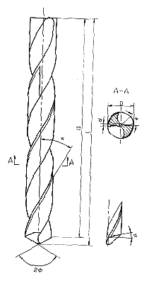
Figure 1 Twist drill structure and geometric parameters 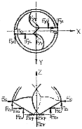
Figure 2 Twist drill cutting
Due to the complex structure of the helical edge cutter, the traditional design method cannot perform accurate strength, stiffness and stress analysis on the tool. In the CAD of the spiral edge cutter, we use the finite element method to analyze and calculate the tool, and study the rationality of the geometrical parameters of the tool from the viewpoint of stiffness, strength and stress. Under the premise of satisfying the cutting conditions, the target is the minimum deformation and the maximum stiffness. Get the best tool geometry to improve its cutting performance. The spiral edge cutters we analyzed include twist drills, end mills, reamers and various non-standard tools. This article introduces the finite element analysis process with twist drills as an example. First, the structural characteristics and stress of the twist drill
Ordinary twist drill is the most commonly used spiral cutting hole machining tool, its structure and geometric parameters are shown in Figure 1. The straight main cutting edge of the twist drill is very long and extends almost to the center of the drill bit; the number of teeth is small, only two, the two main cutting edges are connected by the chisel edge; the two chip grooves are spiral to facilitate chip removal. The two flank faces are part of a conical or helicoid. The main geometric parameters of the twist drill: diameter D , working part length L (including cutting part length L 0 and guiding part length L 1 ), helix angle q , apex angle 2 f , chisel edge angle y , back angle a and core Diameter d .
The force of the twist drill is more complicated when cutting. When drilling, main force twist and deformation resistance of the workpiece material and twist under the forces of friction between the chips and the hole wall, on each cutting edge will be F x, F y, F z three The effect of the cutting component is shown in Figure 2. Ideally, F x is substantially balanced with each other and the remaining forces are axial and circumferential forces. The circumferential force constitutes torque and consumes the main power. The twist drill produces transverse bending, longitudinal bending and torsional deformation under the action of cutting force, and the torsional deformation is most remarkable. Torque is mainly generated by the cutting force on the main cutting edge, which accounts for about 80% of the total torque; the length of the chisel edge is shorter, and the torque generated is about 10%. The axial force is mainly generated by the chisel edge, which accounts for about 50% to 60%; the axial force on the main cutting edge accounts for about 40%. Second, finite element analysis
We used the SAP5P software developed by the Department of Mechanics of Peking University to analyze and calculate the deformation of the twist drill.
The SAP5P program offers a variety of unit types. Since the twist drill is a three-dimensional solid structure, eight types of three-dimensional isoparametric elements with variable number of nodes are selected, and each unit takes 8 to 21 nodes as needed for calculation.
The cutting taper of the twist drill is the main force receiving body, and the load mainly acts on the main cutting edge. Therefore, the cutting cone can be divided into thinner parts when dividing the unit, and the guiding part can be divided thicker and guided from the taper and the guide. Some of the joints began to gradually become dense. The unit division of the twist drill is shown in Figure 3. Since the cutting cone is approximately a cone and the chisel is only a straight line, there is necessarily a problem of transitional connection between the units. As shown in FIG. 4, a node (node ​​28) is constructed in the middle of the taper portion, and a hexahedron is formed through the node and the chisel edge, the two flank faces, and the two grooves. The hexahedron is divided into 8 cells, and the taper is The guide portion is joined at a cross section, and eight units are constructed between the cross section and the hexahedron, so that the cutting cone is divided into 16 units. 
Figure 3 twist drill unit division diagram 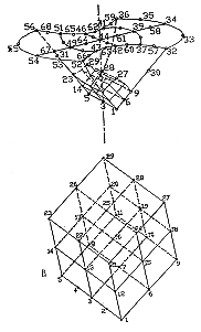
Figure 4: Cutting cone unit division diagram 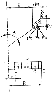
Figure 5 Main cutting edge load distribution map
The guiding portion is a cylinder with two spiral grooves. The solid segments of different heights are intercepted along the axial direction, and each segment is divided into 8 20-node units. According to the computer capacity and twist cutting length, select the corresponding number of physical segments and the number of units.
The node coordinates are calculated based on the actual structure of the twisted taper.
The outer diameter of the guiding portion is substantially the same, except that the upper layer of the solid segment is rotated by a certain angle with respect to the lower layer along the spiral. Let the coordinates of the lower nodes of any unit be X ( i ), Y ( i ), Z ( i ); the coordinates of the upper nodes are X ( j ), Y ( j ), Z ( j ), then
X ( j )= X ( i )cos f - Y ( i )sin f
Y ( j )= X ( i )cos f + Y ( i )sin f
Z ( j )= Z ( i )+ h
Where f =( h / r )tg w , h is the cell thickness (ie the height of the solid segment), r is the radius at the outer circle of the drill bit, w is the helix angle, and  is the angle at which the lower node of the element rotates along the spiral.
The force of the twist drill is more complicated, so the load can be simplified. The following two calculations are performed in two loading modes.
Among them, HB is the hardness of the workpiece material to be processed, and f is the drilling feed amount (mm/r). Then the load assigned to the corresponding node of the main cutting edge is approximately
Let P be the unit radius length load, then 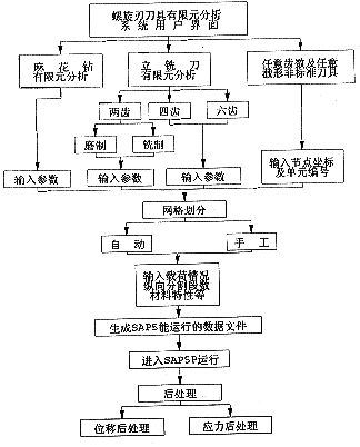
Figure 6 finite element calculation flow chart 
Figure 7 twist drill deformation map
Normal force P n = (0.5 ~ 1.0) P t
Radial force P r = P n cos f
Axial force P a = P n sin f
P 1 = PR /6
P 2 =4 PR /6
P 3 = PR /6
When using the SAP5P program to analyze and calculate the twist drill, only the cutting part and the guiding part are calculated, ignoring the influence of the handle. Therefore, in the overall analysis, the nodes at the joint of the shank and the guiding part should be fixed with the fixed end constraint to limit the degrees of freedom in the six directions; for other nodes, the translational freedom in the three directions of X , Y and Z is given. Degree, limit the degree of freedom of rotation in the three directions of X , Y , Z.
We have written the pre-processing general interface program in Borland C language. The user only needs to input the main geometric parameters of the twist drill. By running the pre-processing program, the grid can be automatically divided and the data files for SAP5P operation can be automatically generated. The finite element calculation process is shown in Figure 6. Third, the calculation results
The three sets of twist drill parameters as shown in Table 1 were selected for calculation. The elastic modulus E = 2.15 × 10 5 /mm 2 , the shear modulus of elasticity G = 8.05 × 10 4 N / mm 2 , the wave-sampling coefficient μ = 0.25, the load calculation is HB = 200, f = 2.5 mm / r, P n = 0.75 P t . Serial number Diameter D
(mm) Core d
(mm) Long working hours
L (mm) Helix angle
w Lateral bevel
y Top corner
2 f Back corner
a 1 14 2.0 108 30° 55° 118° 11° 2 20 2.9 140 3 25 3.0 160 Core thickness
d (mm) Stiffness D 0
(Nm/rad) Helix angle
w Stiffness D 0
(Nm/rad) 2.6 7.625×10 4 20° 5.941×10 4 2.9 7.917×10 4 30° 7.917×10 4 3.0 8.493×10 4 40° 1.014×10 5 3.5 9.022×10 4 50° 1.222×10 5
Enter the three sets of parameters into the pre-processing program to generate a data file for SAP5P to run and enter SAP5P for calculation. The deformation diagram of the twist drill is shown in Figure 7. It can be seen from the output displacement and deformation map that the maximum deformation occurs at the outermost end of the main cutting edge, that is, at node 32 (56).
Taking the twist drill with diameter D = 20mm as an example, the core thickness and the helix angle are changed respectively, and other parameters are unchanged, and the calculation is carried out into SAP5P. The results are shown in Table 2. Figure 8 shows the D 0 - d curve, and Figure 9 shows the D 0 - w curve. 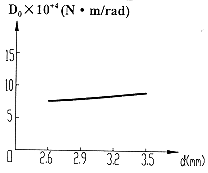
Figure 8 D 0 -d change curve 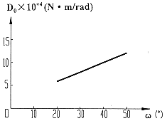
Figure 9 D 0 - w curve Fourth, the conclusion
Taking the twist drill as an example, the influence of the change of the main geometric parameters of the helical edge cutter on the torsional stiffness is analyzed by the finite element method. It can be seen from the calculation results that the geometrical parameters of the twist drill are different, and the deformation amount and the stiffness value are different. As the core diameter and the helix angle increase, the deformation amount gradually decreases, and the stiffness value gradually increases, so that it can be selected. The tool geometry that minimizes the amount of deformation and maximizes stiffness, thereby improving the cutting performance of the tool.