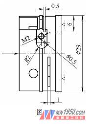
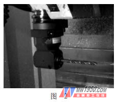
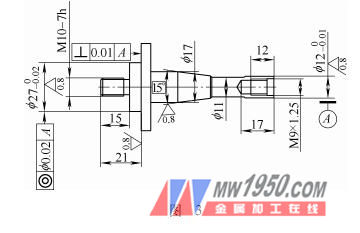
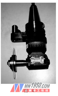
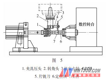
An important part of our company has large batch size, short delivery time, small part size and more processing content, as shown in Figure 1, M2 thread on the side of the part, 0.5 mm narrow groove (depth 6m m), φ Difficult to process content such as 0.5mm small hole (depth 5mm). The side process is dispersed, the process is too long, the quality is not easy to control, and the pass rate of the product has not been ideal. After detailed technical demonstration, our company has carried out a full CNC transformation. Due to the limited space, only the innovative application of the 90° corner head is introduced here, and I hope to help such problems. 1. Process analysis The parts shown in Figure 1 are made of aluminum, machined with 0.5mm grooves, and have a depth of 6mm. The aluminum material is sticky and easy to stick. The original process plan is to use a small bench milling machine, which is processed with a 0.5mm piece milling cutter, which basically meets the processing requirements, but with the transformation of the entire workshop, the processing plan also changes with the layout according to the production line. In order to adapt to modern management, the new workshops all introduce vertical machining centers and CNC slitting machine tools, eliminating ordinary equipment such as bench milling, trolleys and bench drills, which greatly saves space. The production line layout is more compact and reasonable. The groove is completed by a 90° corner head on the vertical machining center and the other side processes. 2. The choice of 90° corner head Since there is a bevel gear reversing mechanism inside the corner head cutter body, it has a certain weight, so it is not suitable to choose a too large model. Otherwise, the tool magazine may lose the weight when the tool change is overweight. After comparison, we chose a 7mm inner diameter of the chuck. The corner head speed can reach 6000r/min. The general application is to clamp the drill hole to machine the side holes or clamp the small diameter end mill to machine the side groove or side hole chamfering, tapping and so on. Figure 2 shows the corner head of a φ7mm drill bit mounted on a CNC machine. 3. Homemade mandrel, innovative application In order to process the 0.5mm×6mm deep groove, we took out the corner clamp spring and made a mandrel by accurately measuring the clamp spring and the taper of the inner hole of the corner head (see Fig. 3), and inserting the mandrel into the corner head. The nut is tightly backed and the front is fitted with a 0.6mm × φ80mm saw blade milling cutter (specially ground), which is tightened with a nut. The chip milling cutter must be sharpened sharply, and the cutting fluid is sufficient to avoid the tool milling too deep and sticking the knife, resulting in a large groove width and a large surface roughness value on the side of the groove, and the most serious may cause the chip milling cutter to collapse. Therefore, after a certain number of chip milling cutters are processed (generally processing thousands of pieces without any problem), if the groove surface roughness is abnormal and the sound is abnormal, the chip milling cutter should be replaced in time. When considering the non-interference between the tool and the fixture, the design of the mandrel should be as short as possible to prevent the tool from interfering with the tool bank when the tool is changed on the tool magazine. The diameter of the milling insert should be as small as possible so that it can be increased. The rigidity of the tool also reduces interference. Figure 4 is an assembled view of the mounting mandrel and the face milling cutter. 4. Practical application The machining diagram is shown in Figure 5. After the corner head is installed, the side busbar of the chip milling cutter jumps at 0.01mm. After the tool is turned up, the blade jumps within 0.05mm. The tool runs at low speed for a period of time, allowing the gears in the tool to run in at different low speeds. It can't be added to a few thousand turns at once to prevent damage to the tool. Because the diameter of the chip milling cutter is large, the blade width is narrow, and the rotation speed is not too high, the rotation speed value is tested to 1200 r/min, the feed speed is 300 mm/min, and the cutting speed is once. The finished surface roughness value and groove width of the groove are all in accordance with the pattern requirements. 5 Conclusion The use of various angle heads largely solves the difficulty of vertical and horizontal conversion of workpieces on the vertical machining center, realizing all the operations of the upper and the side at the same time, improving the precision and reducing the repetitive clamping. And increase the cost of the machine. Using the self-made mandrel to install the chip milling cutter, the new usage of the angle head was found, and a new breakthrough in the process was realized, which has certain application value. (The author is from Beijing North Hongqi Precision Machinery Manufacturing Co., Ltd.) Ceramic Cutting Disc,Ceramic Tile Cutting Disc,Grinding Wheel For Ceramic Tile,Ceramic Grinder Blade Hengshi Diamond Tools CO.,LTD , https://www.ryomaltools.com