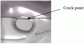
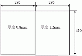
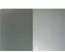
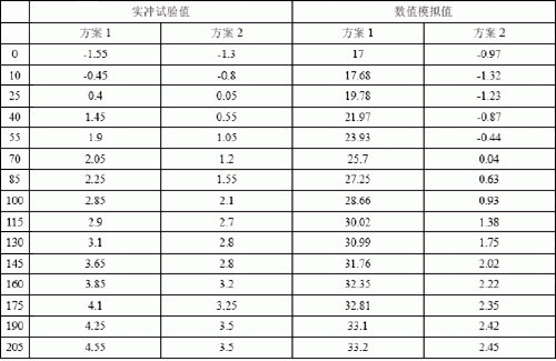
As can be seen from Figure 1, the weld is cracked due to the flow of the weld. It can be seen that it is of great significance to study the flow phenomenon of laser welds during stamping. 1. Experimental materials The material used in this experiment is cold-rolled steel sheet, and its chemical composition is shown in Table 1 below. The thickness of the experimental material was 0.8 mm and 1.2 mm laser splicing. Table 1 Chemical composition of experimental materials 2, experimental methods 2.1 Laser welding For the above-mentioned 0.8 and 1.2 mm difference thick materials, laser welding, due to the small diameter of the laser beam spot used in the test and the thinner steel plate to be welded, laser cutting was used to prepare the edge portion in this study. The prepared side can meet the requirements of the edge quality during laser tailor welding. In this test, the experimental materials were laser welded using a PRC CO2 laser. The laser welding power is 4000W, the welding protection gas is helium gas, the sample laser welding speed is 3400mm/min, and the focusing focal length is 220mm. Figure 2 shows the sample size and test piece after laser welding. 2.2 Numerical simulation and test plan The drawing depth of the blank tailored blank is set to 90 mm, and the forming relative height can be expressed by h/r (where h is the forming height and r is the corner radius of the part), and its h/r value is approximately equal to 2. Using DynaForm software, two schemes: common blanking ring and scheme 2: thickness-changing crimping ring are used to simulate the weld movement, thickness variation and stress strain during the stamping process of laser tailor welded parts. The actual punching test of the actual laser tailor welded blank parts is compared with the simulation analysis results. 3 Discussion 3.1 Maximum weld movement and material flow Taking the direction perpendicular to the initial weld (XX direction) as the reference direction, the material flow and the weld movement are all along this direction. If the material flow or the weld movement is opposite to this direction, it is indicated by the "-" sign. Figure 3 is a schematic diagram of material flow distribution after simulation simulation using two schemes. In the figure, the left side is a 0.8 mm thick sheet and the right side is a 1.2 mm thick sheet. It can be seen from the figure that the thick side material inflow caused by the scheme 1 is the least, and the thin side material also flows in the scheme 1 at the most, thereby correspondingly causing the amount of weld movement to be the most in the scheme 1. Table 2 shows the movement values ​​of the points measured on the weld after the numerical simulation and the actual impulse test under the two schemes. Table 2 Experimental values ​​and numerical simulation values ​​of weld movement under two schemes It can be seen from the table that the error between the actual test value and the numerical simulation value is larger, and the error between the actual test value and the numerical simulation value is smaller, and the numerical simulation can be more accurate. The amount of predicted weld movement. 3.2 Thin side sheet maximum thickening rate In the stamping process, the wrinkles are generally easy to occur on the thin side material. Therefore, the maximum thickening rate of the thin side material under the two schemes in this study is numerically simulated, as shown in Table 3. The degree of influence of different schemes on the wrinkling trend of laser tailor welded blanks. Table 3 Maximum thickening rate of thin side materials under two schemes It can be seen from the numerical results that with the scheme 2 stamping, the maximum thickening rate of the tailor welded blank is less than that of the scheme 1. This indicates that the wrinkle trend of Option 1 is the largest, while Option 2 helps to reduce the wrinkling trend. 3.3 Maximum tensile stress of sheet Table 4 and Table 5 respectively show the maximum radial tensile stress and the maximum tangential tensile stress of the laser tailor welded blank after forming different schemes. It can be seen from the numerical results that the maximum radial tensile stress and the maximum tangential tensile stress of the scheme 2 are smaller than that of the scheme 1, so that the scheme 2 has a certain effect on improving the weld flow. Table 4 Maximum radial tensile stress under two schemes Table 5 Maximum tangential tensile stress under two schemes 4 Conclusion (1) Numerical simulation can predict the phenomenon of weld flow during the stamping process of laser tailor welded blanks. (2) For the laser tailor welded blanks, during the stamping process, by special treatment of the blanking ring, the number of weld movements during the forming of the laser tailor welded blank can be reduced, thereby reducing the wrinkling of the thin side material and reducing the maximum pulling. The stress and the strain at the dangerous point ultimately improve the formability of the tailor welded blank. Our Farm Replacement Parts is good in quality and competitive in price. We are manufacturer and supplier of Farm Replacement Parts following your specific requirement. We are looking forward to your
E-mail and establishing cooperative relationship with you! We would
provide professional Farm Replacement Parts with good services for you! Farm Replacement Parts, Agricultural Replacement Parts, Farm Equipment Replacement Parts Ningbo Borine Machinery Co.,Ltd. , https://www.borine-agroparts.com
Figure 1 Cracking caused by weld flow 


(a) Size of tailor welded blanks (b) Laser tailor welded blanks for experimentsFig. 2 Numerical simulation and experimental tailor welded blanks 
(a) Material flow distribution diagram under Option 1 (b) Material flow distribution diagram under Option 2 Figure 3 Material flow distribution diagram of Scheme 1 and Option 2 


Automotive laser tailor welded blanks are a technology that has developed rapidly in recent years. At present, there are more than 100 tailor welded blank production lines distributed around the world. The application range is also from simply solving the problem of insufficient sheet width, and gradually tends to be different. Thickness, different materials and tailor welding of different surface treated steel sheets. It is about to be stamped into parts by several pieces of different thickness and different strength plates, and then welded into a single piece. The process is to first punch and weld the plates of different strengths and thicknesses into a whole blank, and then perform integral stamping. This plays an important role in reducing vehicle weight, reducing processing steps, reducing costs, increasing production efficiency, and reducing material consumption. The method of laser tailor welding reduces the number of original stamping processes, and now it is changed to one stamping forming, which plays a certain role in controlling the scrapping rate of sheet metal forming, but at the same time, due to the hardening of the laser welded joint, the stamping process is also brought. Certain challenges. One of the problems is the flow of the weld during the stamping process. This requires the possible flow of the weld to be considered in the design of the mold, so that the design structure is reasonable. Figure 1 shows the stamping and cracking of parts due to the fact that the mold design does not take into account the weld flow phenomenon.